|
|
|


|
|
3D profile sensors Matrox AltiZ
DescriptionMatrox AltiZ at a glance:
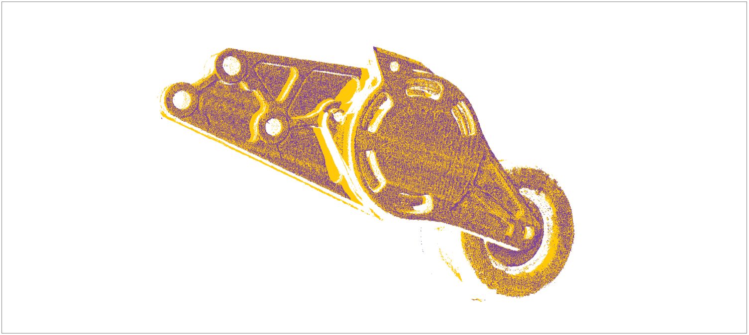
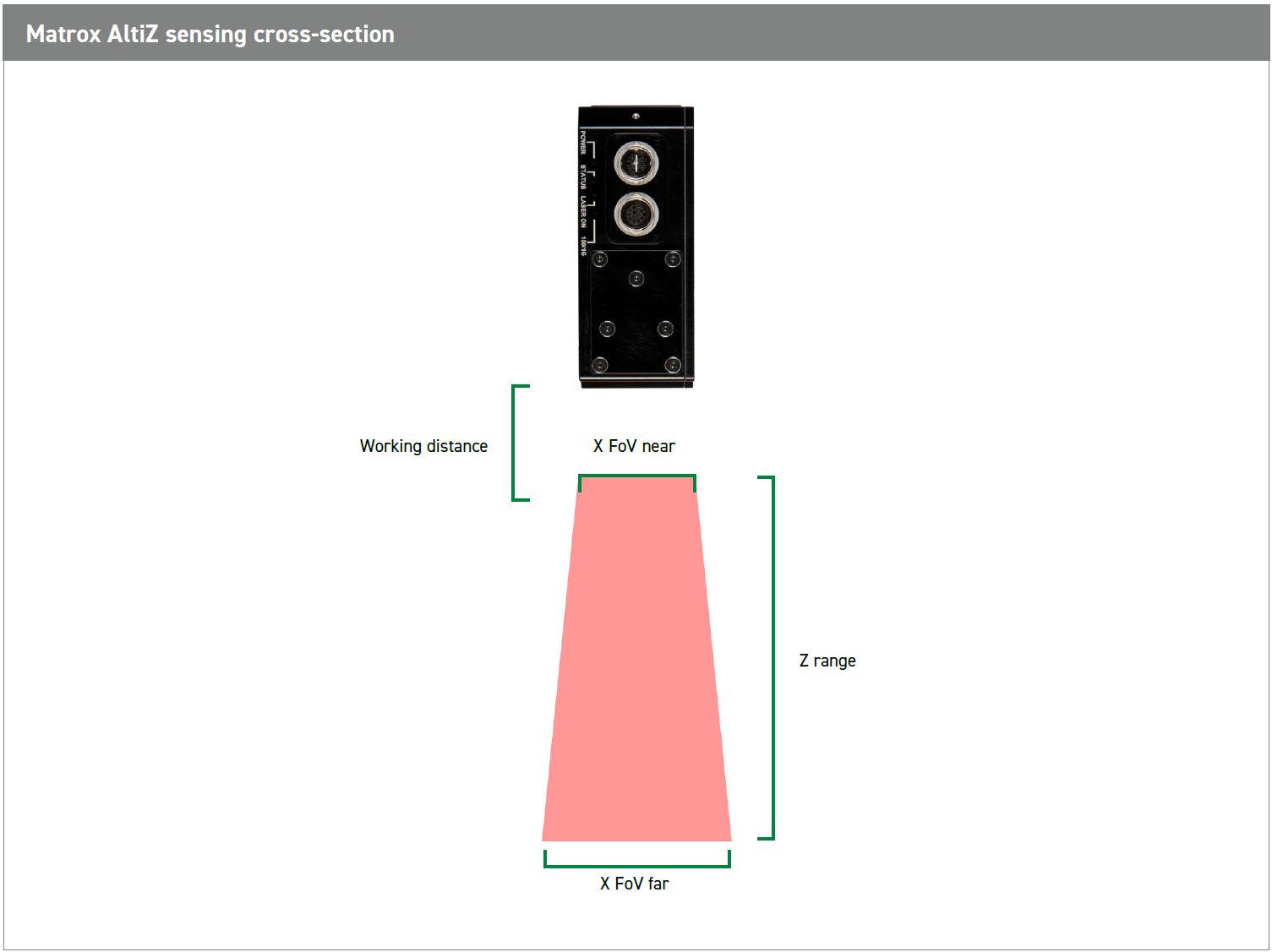
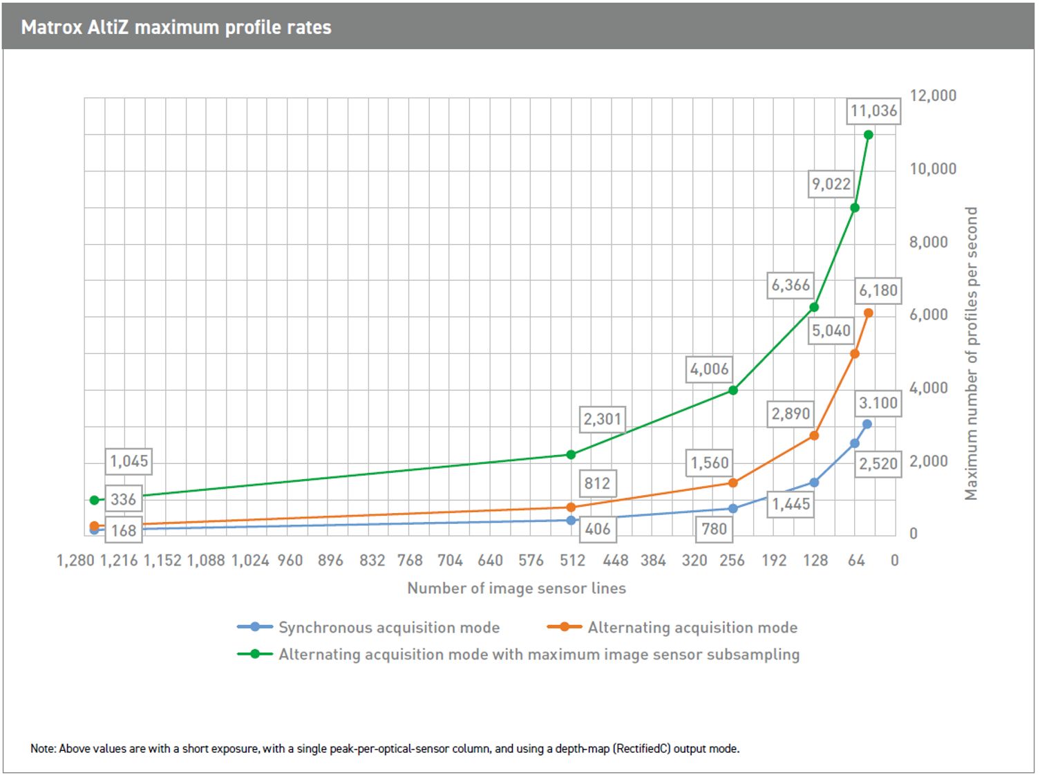
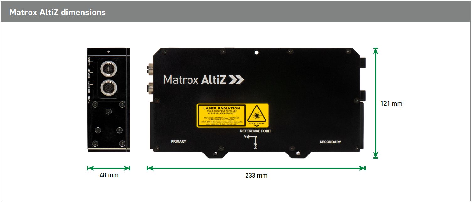
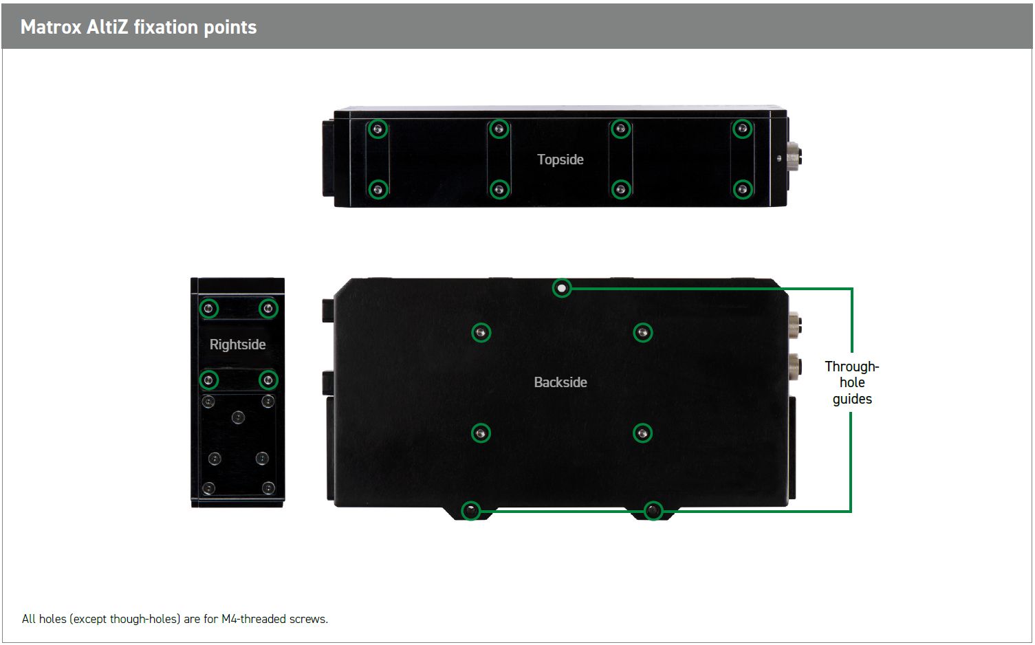
Flexible operation and intuitive setup The two cameras within a Matrox AltiZ can operate either synchronously or in alternation. The former provides maximum reproduction quality and robustness; the latter delivers a scanning rate twice that of the former while still providing some defense against occlusion. The scanning volume — affecting the scanning rate — is set in convenient real-world units. An internal object detection mechanism is available to automatically and optimally start and stop scanning to simplify operation by eliminating the need to supply an external trigger to inform of the presence of an object. Standard interface, discrete I/Os, and power The command and data interface of a Matrox AltiZ is done via a Gigabit Ethernet port with the GigE Vision communication protocol. The sensors’ 24 V-compatible digital I/Os are present for connecting to an incremental encoder and synchronizing multiple 3D sensors, which is useful when there is need to scan different sides of an object or surfaces larger than can be covered by a single 3D sensor. Matrox AltiZ supports PoE for simpler cabling but also features an alternate 24 V power input. Available as a separate accessory, the Matrox I/O Breakout Box simplifies the connection of a Matrox AltiZ by giving convenient access to the digital I/Os through terminal blocks. The I/O breakout box comes with push buttons and switches for testing connections; it can also power one Matrox AltiZ if PoE is unavailable, and be mounted on a standard DIN rail. This accessory is also included in the Matrox AltiZ starter kit, a bundle of all the accessories needed to get going quickly with the Matrox AltiZ. Solid construction and varied mounting Matrox AltiZ features a sturdy IP67-rated2 aluminium housing with M12 connectors that make it perfectly suited for harsh industrial environments. Isolated discrete I/Os provide protection against improper electrical hookup. Back, side, and top attachment points accepting M4-threaded screws are available for fixing a Matrox AltiZ to gantries and robots. Through-hole guides are also included to enable higher-accuracy installation and the alignment of neighboring Matrox AltiZ units. 3D line profiling 3D line profiling is a long-standing and well-established technique for generating a three-dimensional representation of an object. It uses the principle of laser triangulation whereby an image sensor views a laser line that projects onto an object. The laser line bends to follow the contour of the object, which results in a profile; this profile is analyzed to compute the depth or height along the width of the laser line. Object length is determine by accumulating profiles at regular intervals by either moving the 3D device over the fixed object or the object below the fixed 3D device. Sample part scan
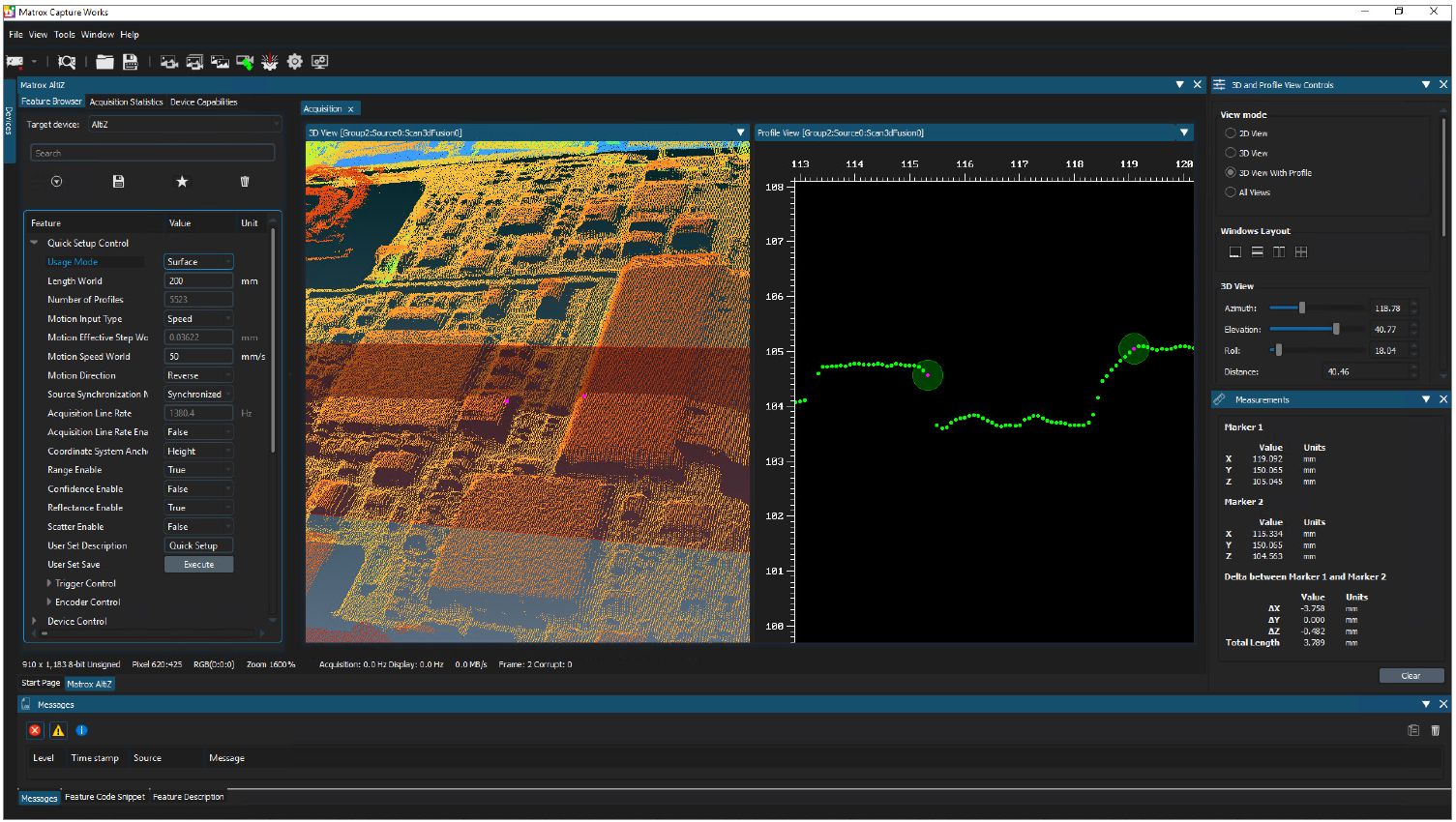
Merged point cloud showing the higher scanning fidelity obtained when using two cameras instead of just one. Zones in solid yellow are only visible when scanning with the two opposed cameras. SOFTWARE ENVIRONMENT Field-proven application development software Matrox AltiZ pairs well with Matrox Imaging Library (MIL) X — a comprehensive software development kit (SDK) for Windows and Linux with a more than 25-year history of reliable performance. This toolkit features interactive software and programming functions for image capture, processing, analysis, display, and archiving. Refer to the MIL X datasheet for more information. The 3D sensors also work with Matrox Design Assistant X, a Windows-based integrated development environment (IDE) based on MIL X, where vision applications result from the construction of flowcharts and their human-machine interface (HMI) from the creation of web pages. Refer to the Matrox Design Assistant X datasheet for more information. Interactive profiler setup Included in MIL X and Matrox Design Assistant X is Matrox Capture Works, an interactive utility for Windows and Linux that enables users to conveniently verify the connection to, as well as configure and test acquisition from, cameras and devices using a GenICam™ - based interface standard such as Matrox AltiZ. Matrox Capture Works contains views specific to the Matrox AltiZ for tuning peak (laser line) extraction, configuring the scanning volume, and setting up device triggering. Third-party software support Matrox AltiZ is also compatible with third-party vision software that implements support for the GigE Vision standard, GenICam GenDC specification, and GenICam PFNC 3D pixel formats. Matrox Capture Works interactive utility
3D (point cloud) view with profile at intersecting plane and measurement markers within the Matrox Capture Works interactive utility.
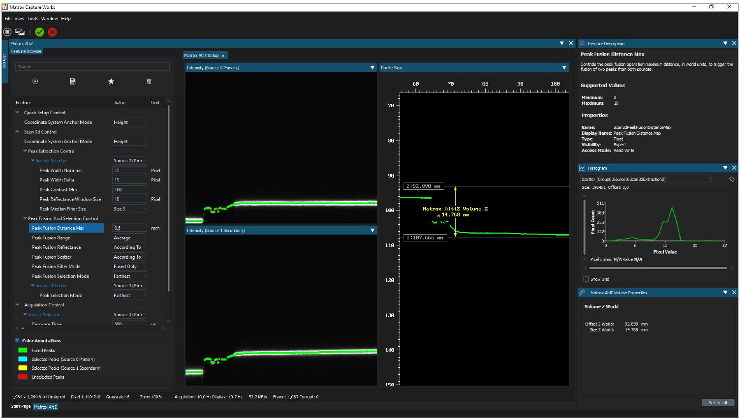
Peak (laser line) extraction, fusion, and volume (Z) adjustment within the Matrox Capture Works interactive utility.
Running time: 4 min 38 sec Endnotes:
1. The product may be protected by one or more patents; see www.matrox.com/patents for more information. Technical specificationMatrox AltiZ sensing cross-section
Notes:
• Values are approximate and may vary slightly between 3D sensors of a given model.
Matrox AltiZ conversion table for number of image-sensor lines to height (mm)
Notes:
• Measured at the far end of Z range, using default peak extraction parameters. Dimensions
ORDERING INFORMATION Hardware
Accessories
Software
Please, contact us for more informations: +48 32 775 0371, info@crijolanta.com.pl or fill and send our contact form. Documents altiz.pdf - English datasheet design-assistant-x.pdf - Matrox Design Assistant X technical description - English datasheet mil10.pdf - Matrox MIL technical description - English datasheet altiz.pdf - English datasheet design-assistant-x.pdf - Matrox Design Assistant X technical description - English datasheet mil10.pdf - Matrox MIL technical description - English datasheetSoftware |
|
|||||||||||||||||||||||||||||||||||||||||||||||||||||||||||||||||||||||||||||||||||||||||||||||||||||||||||||||||||||||||||||||||||||||||||||||||||||||||||||||||||||||||||||||||||||||||||||||||||||||||||||||||||||||||||||||||||||||||||||